GRAVITY GOODS ROPEWAY
Rope laying
Points to remember while laying the wire ropes
along the alignment:
Clear the bushes, trees or other obstacles
before pulling the ropes
Follow the marked alignment while
transporting the ropes from bottom station
to the upper station (leave the mark at the
alignment while surveying)
Do not uncoil ropes from a stationary coil
or reel. Use rotating wheel, drum or disk
to avoid kinking
First, pull the haulage rope along the
alignment then pull the track rope
If there is a river or stream across the
route, do not dip the rope into water
while hoisting
7.7.2 Sag checking
The designed sag can be accurately provided by
marking the saddle points and centre point of
rope before installation.
As the rope inclination is directly proportional to
the sag provided, the required sag can also be
provided by monitoring the rope inclination at
upper saddle (β).
7.7.3 Rope terminals
A) Terminals with drums in concrete
Ropes may be anchored directly into the
foundations with the help of bollards (drums
made out of reinforced concrete) and secured
with bulldog grips. The ropes should be wounded
three times around the drum in order to reduce
the tensile force and to be secured. The minimum
diameter of the drums should be 0.4 m.
B) Terminals with sockets
Sockets should be manufactured from structural
steel (standard quality) conforming to IS 226
1975 specifications having a tensile strength
of 420 to 640 N/mm2 and normalised after the
completion of machining operations and hot dip
galvanised.
Socketing should be made with pure zinc according
to IS 3937 1974 (Part 1), recommended for
socketing of wire ropes.
Sockets can be used as an alternative to thimbles
and bulldog grips for all rope anchorages.
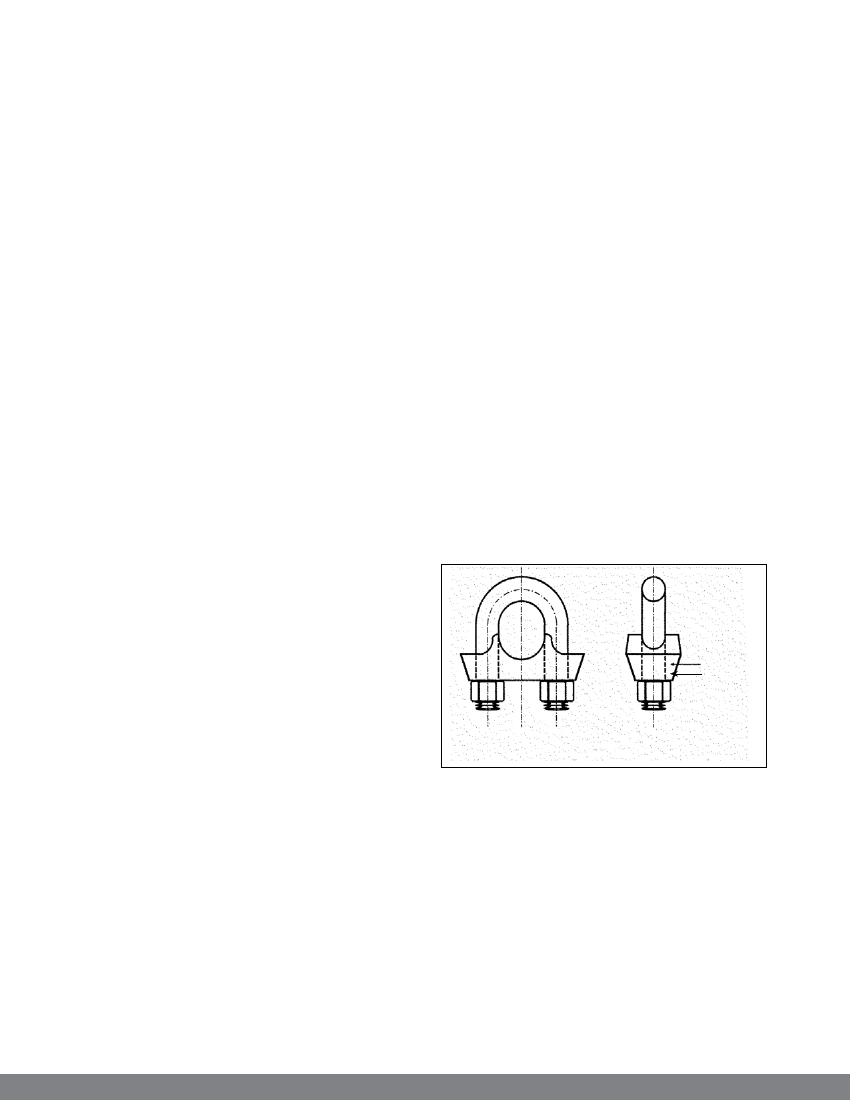
C) Terminals with thimble and bulldog grips
Bulldog grips
These should conform to IS 2361 1970
specifications. The bridges must be drop forged and
suitably scored to grip around strand rope of right
hand lay having six strands. Bridges, eurobonds
and nuts should be hot dip galvanised.
Bulldog grips, when properly applied, afford
a simple and effective mechanical means of
securing the ends of wire ropes, but have to be
inspected after some loadings.
bridge
bulldog grip
Figure 25: A bulldog grip
Thimbles
Thimbles are of open type, conforming to
specifications of IS 2315 1978. They must be
forged and hot dip galvanised. The pin must support
the thimbles. They are necessary to give lateral
support to the strands of the rope at the bend.
The bridge of the grip must be fitted on to the
working part of the rope and the U bolt on to the
rope tail. The first grip must be fitted as close as
possible to the thimble. Grips should be spaced
38